|
|
|
|

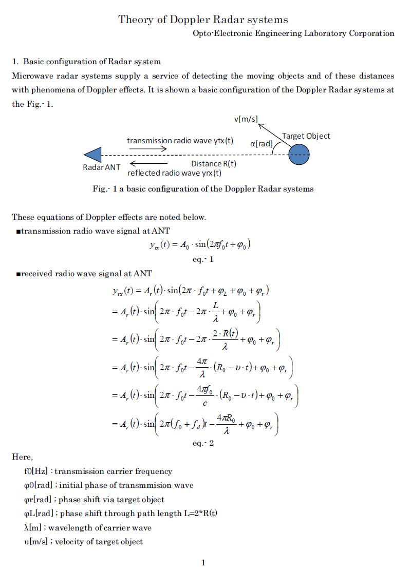
Introduction to Doppler Radar Theory
We have noted the theory of doppler radar systems with system configulation, mathematical equations and FFT analysis.
The doppler radar systems are very useful for the method to measure the velocity of moving objects and to measure the distance
between structural objects.
We provide the technical document relevant to the doppler rador theory.
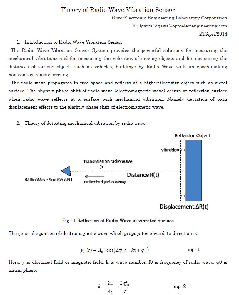
Introduction to Remote Radio Wave Vibration Sensor Theory
We have noted the theory of Remote Radio Wave Vibration Sensor systems with system configulation, mathematical equations.
The Radio Wave Vibration Sensor System provides the powerful solutions for measuring the mechanical vibrations
and for measuring the velocities of moving objects and for measuring the distances of various objects such as vehicles,
buildings by Radio Wave with an epoch-making non-contact remote sensing.
We provide the technical document relevant to the Remote Radio Wave Vibration Sensor theory.
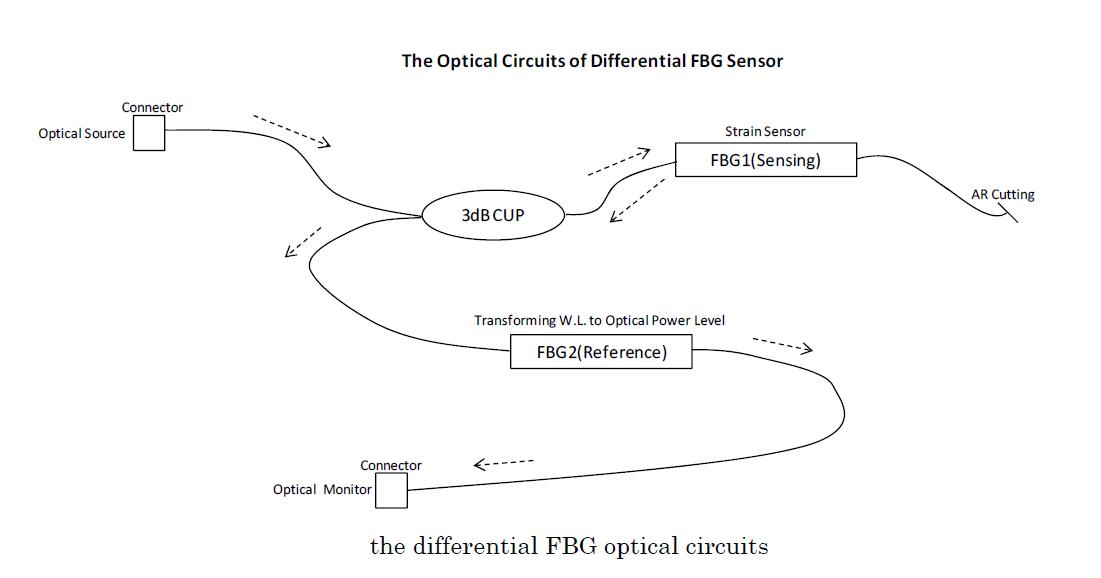
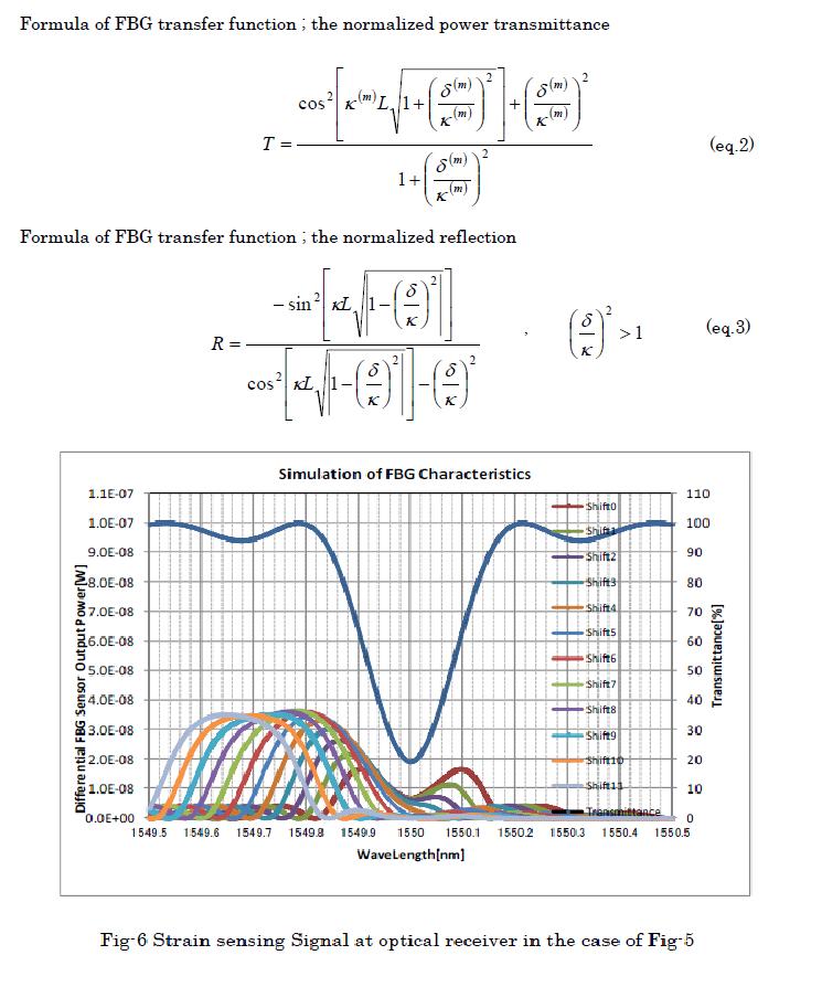
About FBG(Fiber Bragg Grating) and the differential FBG optical circuit
---The principle of the differential FBG optical circuit---
The FBG(Fiber Bragg Grating) is the optical device that is constructed in a short segment of optical fiber
which reflects particular wavelengths of light and transmits all others. The FBG has sensitivity to a temperature and to a external tension stress.
So the FBG is to be useful as a temperature sensor or as a strain sensor. In the case of strain sensor, the temperature factor of FBG is unwanted.
It is necessary to compensate the temperature factor of FBG as for a strain sensor. The differential FBG optical circuit noted below is of great advantage to
the temperature compensate and to its cost. The differential FBG optical circuit consists of complementary pair of two FBGs which cancel mutual temperature
characteristics and provide the function of transforming the optical wavelength to optical power level. Please refer to the document
"The formula of FBG_Fiber Bragg Grating_ characteristics and principle of the differential FBG optical circuit(PDF)".
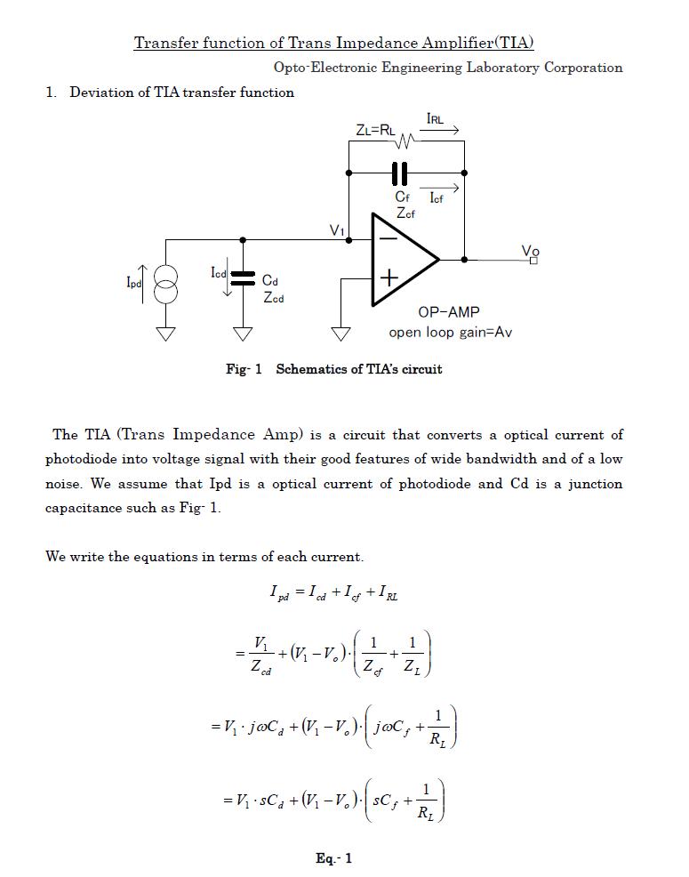
About Transfer function of Trans Impedance Amplifier(TIA) as Photodiode Amplifier
We provide the design document about a transfer function of Trans Impedance Amplifier(TIA) as
the Photodiode Amplifier. The TIA (Trans Impedance Amp) is a circuit that converts a optical
current of photodiode into voltage signal with their good features of wide bandwidth and of a low noise.
Introduction to feed back control
Design method to compensate the stability of feed back loop
; Phase-lag compensation
It is needed to compensate the stability for the feed back loop with a
first-order lag element. A first-order lag element has several features
what has the amplitude decay with −6dB/Oct and the phase-lag with stopping at 90 deg.
The condition for an instability of feed back loop is what the amplitude value at phase-lag 180 deg
region is more than 0dB (>0dB). To the contrary, the condition for an stability of feed back loop is
what the amplitude value at phase-lag 180 deg region is less than 0dB (<0dB).
The phase value of total feed back loop at region of DC and sufficient low frequency is 180 deg, that
is, what a feed back requires indicates a restoring force. So, the phase-lag 180 deg means the total
phase-lag being 360deg in total loop.
What the amplitude value at phase-lag 180 deg region is more than 0dB is indicating that the feed
back signal at specific frequency is growing gradually for every go-around on loop cause of being
with amplitude >0dB. It is needed for the feed back loop’s stability to avoid the conditions what the
amplitude value at phase-lag 180 deg region is more than 0dB (>0dB).
The effect of a first-order lag element for the stability of loop is that keeps the amplitude value
being less than 0dB via the decay −6dB/Oct in the phase lag 90 deg -stopping region.We should keep the
phase margin being more than 45 deg in order to acquire the stability of loop.
We provide the technical document relevant to the feed back control.
Introduction to calculating a digitally controlled PID filter
We supply the application sample code of DSP / TMS320F28335 as to the digitally controlled PID filter
via our "DSP F28335 Basic Control Platform C-Programming Code Sets".
The sample application of the digitally
controlled PID filter is the incomplete integral type having the characteristics of a first-order lag element.
Features and key words ;
- Calculating the design parameter of a digitally controlled PID filter
- Principle of Digitally controlled PID filter
- s-z Bilinear Transform
- Plotting the graph of transfer function for a digitally controlled PID filter
- Corresponding the application sample code of a digitally controlled PID filter
via "DSP F28335 Basic Control Platform C-Programming Code Sets"
Technical Design Document and Calculator for a digitally controlled PID filter ;
*1 ; Not included fee for Bank. Fee for Bank is on customer's responsibility.
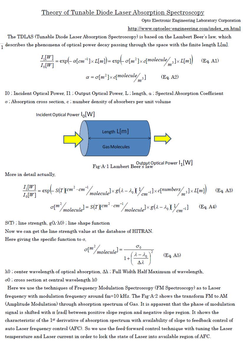
Theory of Tunable Diode Laser Absorption Spectroscopy(TDLAS)
We are good at controlling a Laser diode electrically. We have posted the articles about Theory of Tunable Diode Laser Absorption Spectroscopy(TDLAS).
Please enjoy our technical document as coffee break.
|
|
|
|
|
TOP |
Copyright (C) 2013 Opto-Electronic Engineering Laboratory Corporation. All rights reserved. |
|